When we are using the probe to measure the workpiece, there will inevitably be some error situations. If not detected in time, it may cause defects in subsequent workpiece processing. In this case, it is necessary to calibrate the probe to ensure the smooth progress of subsequent measurements.
There are two main reasons for calibrating the probe: to obtain the compensation diameter of the probe's ruby ball and the relationship between the different probe positions and the first probe position.
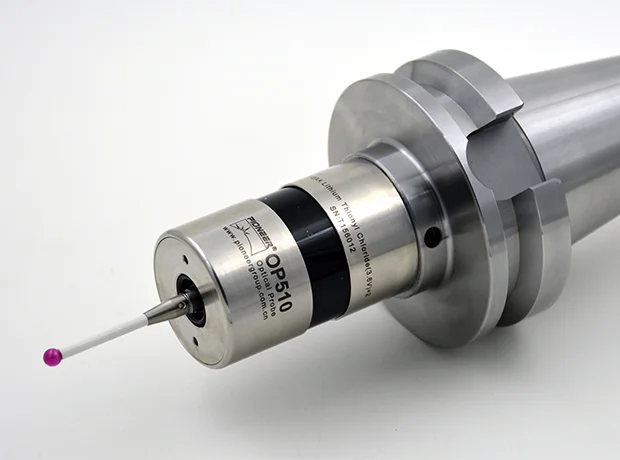
When the coordinate measuring machine is measuring, the ruby ball of the probe touches the measuring part of the measured part. At this time, the probe (sensor) sends a probing signal. After the signal enters the counting system, the current grating counter is latched and sent to the computer, and the measurement software receives a point represented by X, Y, and Z coordinates.
We can understand this coordinate point as the center coordinate of the ruby ball of the probe, which differs from the contact point between the ruby ball of the probe we really need and the workpiece by a ball radius. In order to accurately calculate the coordinates of the contact point we need, we must use the probe to calibrate and obtain the half/diameter of the probe's ruby ball.
Additionally, calibration also extends the life of the probe, such as the spindle probe, and ensures consistency in the performance of the machine tool. Overall, calibration of the probe is an essential maintenance process that guarantees consistent quality output and extends the longevity of the machine tool.
The calibration of the touch probes mainly uses a standard ball. The diameter of the standard ball is between 10mm and 50mm, and its diameter and shape error have been calibrated (the standard balls configured by the manufacturer are equipped with calibration certificates). Before calibrating the probe, the probe needs to be defined. According to the requirements of the measurement software, select (input) the measuring base, probe, extension rod, probe needle, standard ball diameter (the actual diameter value calibrated after the standard ball is calibrated), etc. (some software requires input of the distance from the probe needle to the center of the measuring base), and define the probe number that can distinguish its different angles, positions, or lengths.
Manually, with the operating rod, or automatically, probe at least 5 points within the maximum range of the standard ball (usually recommended at 7-11 points), and the distribution of the points should be even. After receiving these points (the X, Y, and Z values of the ruby ball center coordinate), the computer software performs a fitting calculation of the ball, and obtains the center coordinate, diameter and shape error of the fitted ball.
Subtracting the diameter of the fitted ball from the diameter of the standard ball yields the "diameter" of the calibrated probe ruby ball (more precisely, it should be called "calibration value" or "calibration diameter").
When the probe with different angles, positions, or lengths are calibrated using the above method, the position relationship between each probe can be obtained from the difference in center point coordinates of the fitted ball, and the measurement software generates the probe relationship matrix.
When we use probes of different angles, positions and lengths to measure elements of the same part in different parts, the measurement software converts them to the same probe number (usually the first probe number) as if they were measured by one probe. Any probe that has been calibrated on the same standard ball (at the same position) can achieve this automatic conversion accurately.
 English
  日本語
日本語  한국어
한국어  français
  Deutsch
  Español
  italiano
  русский
  português
  tiếng việt
  Nederland