Camshaft is the core component of the engine. The size and shape of the camshaft is the main factor affecting the valve opening and closing clearance and valve distribution efficiency. In addition, the contour error of its descending section is also one of the reasons for engine noise. Therefore, it is very necessary to detect the geometric tolerance of the camshaft with high precision and efficiency.
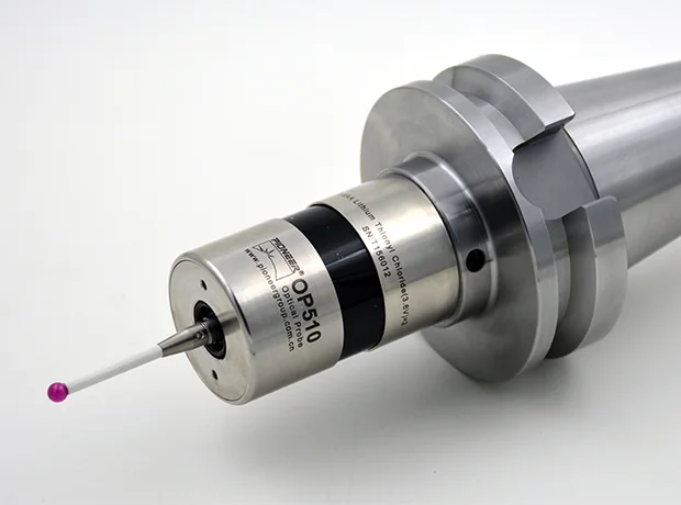
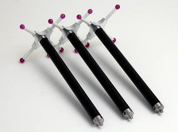
Whether determining the detection position of the cam or measuring the lift of the cam, the same shape of the probe must be selected according to the design requirements. When each cam follower on the same camshaft is different, the same measuring probe is used to measure the cams with different followers, especially in the automatic measurement of the cam. The arbitrary switching of the probe can save the process of replacing the probe in the measurement process, but it also introduces the shortcomings of switching the probe.
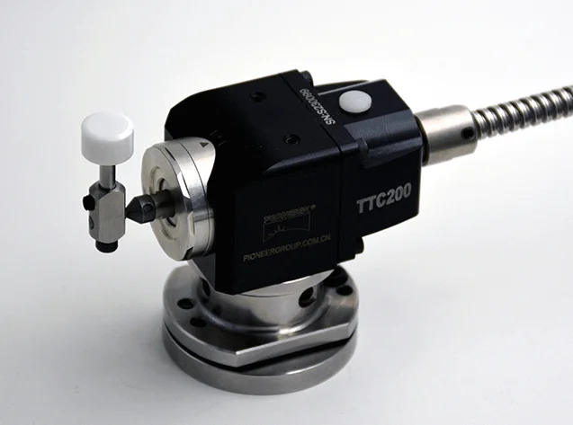
In fact, the change of the touch probe speed depends on the method of installation of the touch probe and the consistency of the changed reference. Combine the touch probe mounting cylinder with the cone, and adjust the installation position of the plane touch probe and the ruler blade touch probe to be consistent with the cylindrical roller touch probe's generator based on the installation position of the roller touch probe. The installation position error of different touch probes should be within 1pm.
The improved touch probe is installed accurately and quickly, does not affect the measurement speed, and is much better than the touch probe switch. This not only ensures that the detection conforms to the motion law of cam design, but also avoids the complex calculation process of solving the equivalent lift table. Its biggest feature is that it can use the original data of previous cam measurement, which is especially conducive to the automatic measurement of cam.
Generally, the machine tool probe that meets the design requirements must be selected, and it is not allowed to switch the touch probe. Of course, on some special occasions, you can also choose a touch probe different from the design requirements for measurement. In order to facilitate the machining and measurement of the cam, the valve lift of the swing cylinder with the rocker arm in contact with the cam profile needs to be replaced by the lift of a pair of central moving plane touch probes.
When calculating the equivalent lift, it must be ensured that the measuring point position on the cam profile before and after touch probe switching is the same, that is, the equivalent measuring point position is the same as the design measuring point position.
Finally, it must be pointed out that the equivalent lifting table with design angle does not consider the consistency between the equivalent measuring touch point after switching machine tool probes and the design measuring point, which is inconsistent with the design requirements of the cam.
 English
  日本語
日本語  한국어
한국어  français
  Deutsch
  Español
  italiano
  русский
  português
  tiếng việt
  Nederland