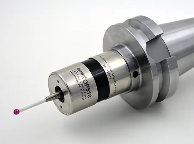
With regard to machine tool probes, it is necessary to regularly determine the installation characteristics of each probe for the first application and subsequent application. In this way, the supporting software can run on the CNC machine tool to compensate the inherent characteristics of the measurement system and accurately calculate the gap correction and workpiece offset. This process of measuring characteristics is commonly referred to as probe calibration in industry.
The importance of good calibration of touch probes for cnc machines is not exaggerated because all subsequent measurements are based on the values determined here. The input error can only be eliminated after a new calibration of the system.
1. The electronic length of the machine tool probes (different from the physical length of the probe). After calibrating the probe, make heading preparation compensation for all subsequent measurements.
2. Measure the electronic radius of the ball (different from the physical size of the ball, this radius also includes a pre course, which is compensated in subsequent measurements).
3. The eccentricity of the needle relative to the axis is the distance between the center of the needle and the axis tool of the machine tool in the x-axis direction. Typically, this distance is compensated by all subsequent measurements. However, for some machine tools, this compensation is impossible, so the bias must be minimized by mechanical means.
Although there are many probe calibration methods, the calibration procedure of each method is basically the same.
We will first introduce a widely used method: this method is basically used by machine tools with return stroke axis (five axis machine tools).
Typical sequence:
1. The measurement system must be installed and calibrated in accordance with the manufacturer's recommendations.
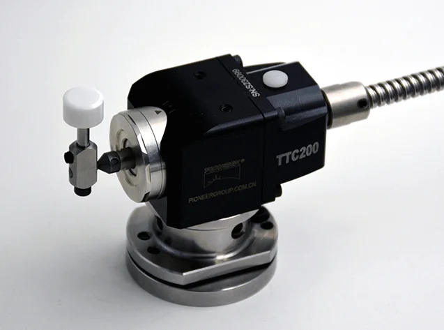
2. Before installation, for machine tools without shaft orientation, optimization is crucial for the adjustment in progress (i.e. minimizing the eccentricity of the measuring needle ball when the shaft rotates). Eccentricity is usually measured with a small micrometer (in contact with the needle ball), and then adjusted on the connecting surface of the rod with a series of screws.
3. If the machine tool probes measurement software cycle program (macro program) is not installed on the CNC machine tool, it must be loaded according to the instructions.
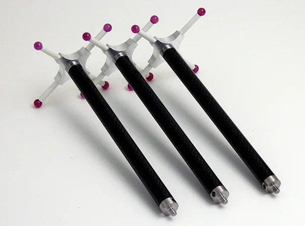
4. A test rod (long rod) of known exact length is required to be installed on the machine. The length of the test rod (usually engraved on the rod and confirmed by the calibration certificate) must be entered into the corresponding auxiliary register.
5. A ring gauge with known accurate diameter is required to be firmly fixed on the workbench of the machine tool. The diameter of the template must be entered in the software cycle calibration procedure.
6. The center of the gauge must be accurately determined on the XY plane. This step can be omitted if the calibration software performing this step provides the possibility of using the axis direction to automatically locate the center. Otherwise, use the micrometer counter (DTI) to determine the center. Install the micrometer at the end of the wellhead and rotate it slowly until a fixed reading is displayed at 360 degrees. Then you must adjust the offset of the current part at the center of the XY plane.
 English
  日本語
日本語  한국어
한국어  français
  Deutsch
  Español
  italiano
  русский
  português
  tiếng việt
  Nederland