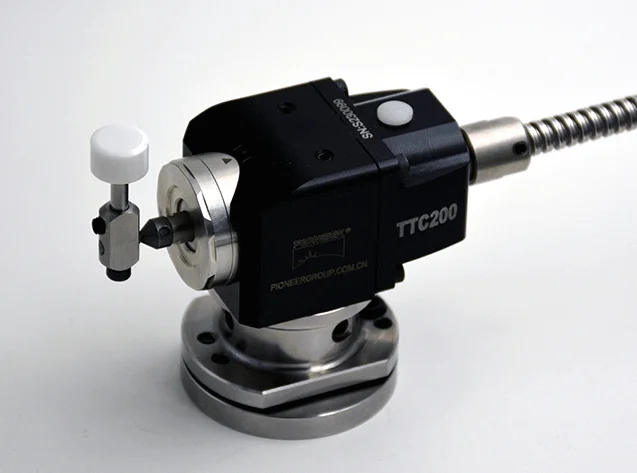
1. The correction of the touch probe height can be completed by two methods:
① Execute the C68 P0 command when the spindle is not equipped with a tool, and the end of the spindle lightly touches the top of the touch probe at the speed set by the system, and the system automatically records the switch point of the probe signal as the reference point for the CNC measuring probe to measure the tool length.
②In the case where the spindle is equipped with a tool with a known precise tool length (this tool length has been entered in the corresponding tool length column in the tool table in advance), execute the G68 P5 command, the tool touches the top of the probe lightly, the system records the data, and completes correction for probe height.
2. Calibration method of touch probe head diameter
A tool of known exact length and diameter is loaded into the spindle. Because the main shaft does not rotate when calibrating the touch probe, in order to avoid the calibration misalignment caused by the contact of the milling cutter groove with the probe, a finely ground round iron rod is used instead of the milling cutter.
Execute the G68P6 RxxAx command, where: R indicates the minimum horizontal distance between the tool and the cylinder at the top of the probe when the tool approaches the probe in the vertical direction; A indicates the vertical distance between the bottom end of the tool and the upper surface of the cylinder at the top of the probe during calibration. The tool automatically collides with the side of the touch probe in four directions +X, -X, +Y, -Y, and the system automatically records the data to complete the correction of the probe head diameter.
3. After the calibration of the touch probe is completed, its height and head diameter data are automatically defined in the cycle parameter table.
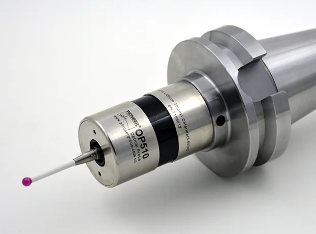
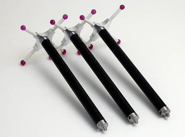
1. Calibration of spindle probe rod and probe tip
When the spindle probe is adjusted to the spindle, due to the manufacturing and installation errors of the probe, the center line of the probe rod will not completely coincide with the spindle axis, and the actual size of the probe tip will not coincide with the nominal size set in the tool table. will be exactly the same, which will cause a large error in the actual measurement. Therefore, the probe must be calibrated before use and after a period of use.
The correction of the probe rod and the probe tip includes two parts, that is, the deviation of the center line of the probe rod relative to the spindle axis and the effective dimensions of the probe tip in the four directions of +X, -X, +Y, -Y (the horizontal distance between the contact point of the probe tip and the workpiece and the center line of the probe when measuring the workpiece). These two parts of the deviation can be corrected by the G72 command at the same time. The calibration steps are as follows:
①Set the tool type of the tool position where the probe is located in the tool table to Probe. The nominal diameter of the tool is set to 6mm (the diameter of the ball at the tip of the probe is about 6mm). To clamp a workpiece with a hole on the workbench, the exact diameter of the hole and the coordinates of the center line must be known in advance. The hole of the workpiece can be obtained by fine boring, or a standard gauge can be used to press it on the worktable, and the centerline position can be found with a dial gauge (put the dial gauge into the table seat, the table seat is adsorbed on the end surface of the spindle, and rotate the spindle). For more accurate calibration, the centerline of the gauge should be as close as possible to the axis of the spindle, and the diameter of the hole should be as large as possible.
②Execute the TxM6 command to transfer the probe to the spindle. Lightly touch the stem of the probe, if the screen displays "Unexpeted Hit Probe Cycle", it means that the probe is working normally and you can proceed to the next step. Otherwise, it indicates that the probe is not in normal working state, the alarm must be cleared and the probe must be re-adjusted. Then move the probe to the centerline of the reference hole and lower the spindle so that the tip of the probe is fully inside the hole.
③ Execute the G72 Px command (xx refers to the exact diameter of the hole).
④ Adjust the spindle probe to the spindle. Place the gauge block on the table, directly below the upper spindle. Execute the G74 Zxx command (x is the Z-axis coordinate value recorded just now), and the probe will contact the surface of the gauge block along the Z-axis direction. The dynamic length of the probe is automatically stored in the tool table. The probe makes a series of touches in the four directions +X, -X, +Y, -Y to determine the deviation of the probe stem relative to the spindle axis and the actual size of the probe tip. The system automatically records the data. The deviation value of the probe rod is stored in the tool table, and the dimensions of the probe tip in the four directions of +X, -X, +Y, and -Y are stored in the cycle parameter table. In this way, the calibration of the spindle probe rod and the probe tip on the XY plane is completed.
2. The steps to correct the length of the spindle probe are as follows:
① Preparation: Roughly measure the length of the probe with a scale, and the error is within 3mm. Enter this size into the column of tool length corresponding to the probe in the tool table. Remove the tool on the spindle, and T0 is displayed on the screen. Prepare a gauge block with a good parallelism between the upper and lower surfaces, and roughly measure the height of the block.
② Lower the spindle to a position 3 ~ 4mm larger than the measured value. Put the gauge block on the table, and then use the handwheel to move the spindle down with a small magnification until the end face of the spindle is close to the surface of the gauge block.
③Continue to move the spindle to the position where the end surface of the spindle just touches the upper surface of the gauge block (the gauge block can be moved horizontally at this time, but it is difficult), and record the Z-axis coordinate value displayed on the screen.
 English
  日本語
日本語  한국어
한국어  français
  Deutsch
  Español
  italiano
  русский
  português
  tiếng việt
  Nederland